




 About Us
 2026-02-16
Steel structure purlins serve as critical support components for roof and wall panels in steel buildings. Their proper installation directly impacts building waterproofing, structural stability, and service life. Adhering to specifications and employing scientific, rational methods during construction ensures purlins are installed correctly, meet load-bearing requirements, and deliver optimal overall performance. Below we detail the installation process from pre-construction preparation and installation steps to quality control.
1. Construction Preparation
(1) Material Inspection and Acceptance
Verify purlin specifications: Cross-reference purlin models, dimensions, materials, and quantities against design drawings. For common types like C-channels and Z-channels, focus on measuring cross-sectional dimensions and wall thickness to ensure height, width, and other parameters meet requirements.
Quality Inspection: Inspect purlin surfaces, discarding components with cracks or severe deformation. Minor rust requires removal treatment. Simultaneously, verify completeness of documentation including factory certificates and quality inspection reports.
Accessory Preparation: Prepare installation accessories such as purlin support plates, bolts, and nuts. Ensure bolt specifications meet design requirements with no stripped threads or damage.
(2) Construction Equipment Preparation
Lifting Equipment: Select appropriate lifting equipment (e.g., truck cranes, crawler cranes, tower cranes) based on purlin weight and installation height. Verify lifting capacity meets requirements and conduct comprehensive inspections and adjustments to ensure safe, reliable operation.
Installation Tools: Prepare wrenches, screwdrivers, tape measures, levels, theodolites, and other installation tools. Wrenches are used for tightening bolts, tape measures for measuring purlin spacing and installation dimensions, while levels and theodolites control purlin horizontal and vertical alignment.
(3) Site Preparation
Steel Structure Main Frame Acceptance: Prior to purlin installation, the steel structure main frame must undergo acceptance inspection to ensure column and beam verticality, axis deviation, and other parameters comply with design and code requirements. Purlin installation may only proceed after the main structure passes inspection.
Work Surface Preparation: Clear the purlin installation area of debris, oil stains, etc., ensuring a flat, clean surface. Simultaneously, erect necessary work platforms and safety barriers (e.g., scaffolding, safety nets) to provide a secure working environment for personnel.
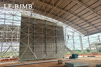
2. Installation Process
(1) Purlin Support Plate Installation
Positioning and Layout: Mark the installation lines for purlin support plates on steel columns or beams according to design drawings. Use a theodolite with a tape measure for precise measurements, ensuring positional accuracy with spacing tolerances controlled within ±5 mm.
Purlin Support Plate Installation: Weld the purlin support plates to the steel columns or beams along the marked lines. Employ symmetrical welding to prevent plate deformation, ensuring the plates are perfectly level and vertical. Weld height must meet design specifications, typically no less than 6 mm. Weld surfaces must be smooth, free of defects such as porosity or slag inclusions. After welding, visually inspect the weld appearance. If necessary, perform ultrasonic flaw detection.
(2) Purlin Lifting and Installation
Purlin Lifting: Use lifting equipment to transport purlins to the installation area. Select lifting points appropriately to prevent deformation. For long purlins, use multi-point lifting to ensure stability.
Purlin Installation: Position purlins on purlin support plates, adjust alignment and height to design specifications, and securely fasten with bolts. Tightening torque must meet design requirements. Adjacent purlins shall be level with height differences ≤3mm and straightness deviation ≤L/1000 (where L is purlin length) and ≤10mm.
(3) Tie Rod and Strut Installation
Tie Rod Installation: Tie rods enhance lateral stability of purlins. Install after purlin completion. Typically made of round steel, tie rods connect to purlin tie holes via bolts at both ends. Ensure tie rods are taut without slack, with precise positioning and deviation not exceeding ±10mm.
Strut Installation: Struts are typically positioned at eaves, ridges, and similar locations to enhance overall purlin stability. Struts generally consist of steel pipes and round steel bars. First, connect the steel pipes to the purlins or steel columns, then install the round steel tie rods to form a stable triangular structure. Struts must be securely installed with tight connections to the purlins.
3. Quality Control
(1) Installation Dimension Control
Spacing Control: Purlin spacing must be installed according to design requirements, with deviations not exceeding ±5 mm. During construction, spacing can be pre-marked on purlin support boards or measured with a tape measure during installation to ensure uniform spacing.
Elevation Control: Purlin elevations must meet design standards, verified and adjusted using a level. Within the same span, elevation deviation between purlins must not exceed ±5 mm, and the height difference between adjacent purlins must not exceed 3 mm.
(2) Connection Quality Control
Bolt Connections: Bolts must be securely tightened with washers placed beneath nuts to prevent loosening. Bolt tightening torque should meet design specifications, verifiable using a torque wrench. For high-strength bolts, final tightening torque checks are required to ensure preload meets design requirements.
Welding Quality: Welding quality between purlin support plates and steel columns/beams is critical. Welds must be full, uniform, and free of defects such as porosity, slag inclusions, or cracks. After welding, conduct a visual inspection of the welds. If necessary, perform ultrasonic testing to ensure weld quality meets requirements.
(3) Anti-Corrosion Treatment
Purlin Anti-Corrosion: Purlin anti-corrosion treatment is completed prior to installation. However, transportation and installation may damage the coating. After installation, repair damaged areas with the original anti-corrosion coating to maintain protective performance.
Corrosion Protection for Welded Areas: Welded joints between purlin support plates and purlins must undergo rust removal after welding. Apply anti-corrosion coating to prevent rust formation at these welded areas.
4. Safety Measures
Personnel Safety: Safety helmets must be worn during construction. Safety harnesses must be worn and securely fastened to sturdy structural components during elevated work. No elevated work is permitted without proper safety measures in place.
Equipment Safety: Inspect and calibrate lifting equipment before use to ensure proper functionality. Follow operating procedures during lifting operations and never exceed weight limits. Establish safety perimeter lines to prevent unauthorized personnel from approaching.
Temporary Electrical Safety: Adhere to electrical standards on-site and install ground fault circuit interrupters (GFCIs). Elevate electrical cables instead of laying them on the ground to prevent leakage and electric shock hazards.


