





 About Us
 2026-06-17
1. Planar Structural Systems
(1) Beam Structures
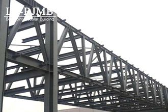
A beam is a linear member that bears loads perpendicular to its longitudinal axis. Its cross-sectional dimensions are smaller than its span length, and it is primarily subjected to bending and shear. A single-plane lattice truss can be regarded as a single load-bearing member; from a macroscopic perspective, its load-bearing behavior is similar to that of a single beam. Therefore, structures consisting of beams and single-plane lattice trusses are collectively referred to as beam structures. The recommended span for beam systems should be less than 60 m; as the structural span increases, their economic efficiency decreases due to excessive steel consumption.
(2) Rigid Frame Structures
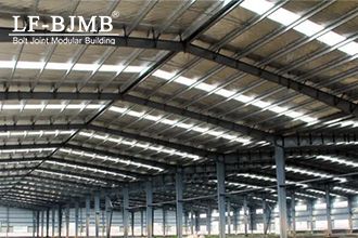
Rigid frame structures refer to structures in which beams and columns are rigidly connected; they can be specifically classified into solid-web rigid frames and lattice rigid frames. Solid-web rigid frames are suitable for building structures with relatively short spans, typically ranging from 18 to 60 m. When the structural span exceeds 60 m, solid-web rigid frames become economically unfeasible; in such cases, lattice rigid frames can be used, which can span over 100 m. Rigid frame structures offer flexible design options and provide ample interior space, making them widely used in industrial plants, sports arenas, auditoriums, and other buildings.
2. Spatial Structural Systems
(1) Space Structures
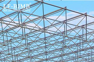
A space frame is a spatial truss structure—either flat or slightly curved—formed by members arranged according to a specific pattern and connected at joints.
There are many forms of space truss structures. Based on the number of chord layers, they are typically classified as double-layer, triple-layer, or multi-layer space trusses; based on support methods, they include perimeter-supported, point-supported, tree-supported, and mixed-supported forms; and based on grid composition, they include cross-truss systems, four-corner cone systems, and triangular cone systems.
(2) Shell Structures
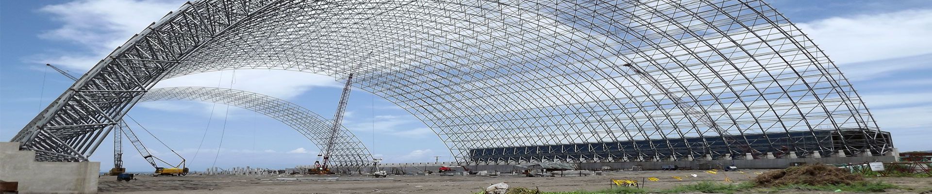
Common shell structures are generally classified into two types: double-layer and single-layer. A double-layer shell structure refers to a geometrically stable system formed by connecting member units through hinged joints according to a specific pattern and applying boundary constraints; a single-layer shell structure refers to a geometrically stable system formed by connecting beam units through rigid joints according to a specific pattern and applying boundary constraints.

(3) Three-Dimensional Truss Structures
A three-dimensional truss structure consists of a lattice truss with a triangular or quadrilateral cross-section, formed by upper chords, web members, and lower chords. Three-dimensional trusses typically take the form of tubular trusses, with structural spans reaching 60 meters or more. These structures are widely used in architectural applications such as sports stadiums, convention and exhibition centers, and transportation terminals.
(4) Cable-Supported Structures
A cable-supported structure is a structural system composed of a series of suspension cables arranged according to a specific pattern, which serve as the primary load-bearing members. Cable-supported roof structures typically consist of three components: the cable system, the roof system, and the support system. Cable-supported structures can be classified into single-layer cable-supported structures, double-layer cable-supported structures, and prestressed cable-net structures.
(5) Membrane Structures
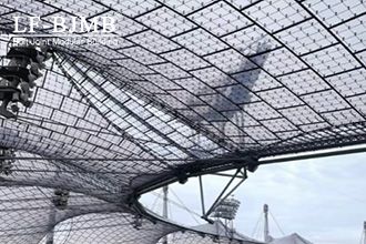
Membrane structures are buildings or structures composed of membrane materials and their supporting components. Membrane structures are classified into monolithic tensioned membrane structures, framed membrane structures, cable-supported membrane structures, and air-supported membrane structures.
3. Construction Methods for Long-Span Steel Structures
(1) High-Altitude Assembly Method
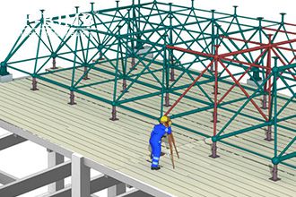
The method of assembling members and joints (or small subassemblies) directly at their designed positions at height to form a complete structure is referred to as high-altitude assembly. Typically, full-area supports (or full-area scaffolding) are set up at the base of the structure, which are then used as supports to complete the assembly of structural components in situ at height.
Characteristics: The structure is assembled in one go at the design elevation. This method is suitable for structures that are not very tall or wide and have a relatively small number of members.
Advantages: Assembly can be completed using simple lifting and transport equipment, or even without lifting equipment at all, making it suitable for regions such as mountainous areas where lifting capacity is limited or transportation is difficult. It allows for easy control of joint coordinates, offers flexible construction, and enables high reusability of scaffolding. Disadvantages: It involves a large amount of on-site and high-altitude work, requires a significant amount of scaffolding materials, results in a relatively long construction period, and occupies a large amount of site space.
(2) Strip-by-Strip or Block-by-Block Installation Method
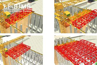
The structure is divided into several strip-shaped or block-shaped units. After each strip or block is assembled on the ground, it is hoisted by a crane to its designed position and assembled into a single unit. This method is known as the strip-by-strip (or block-by-block) hoisting method.
Construction Sequence: First, the structure is divided into appropriate construction sections, and the structure within each section is subdivided into hoisting units. Components and joints are assembled into hoisting units on the ground. Next, based on the section divisions, a construction support system is set up at the section boundaries. Then, hoisting equipment is used to lift the hoisting units onto the construction support system, and additional members are installed as needed. Finally, once the structure forms a complete structural system, the load is removed to bring the structure to its designed state.
Characteristics: Since the strip- or block-shaped units are assembled on the ground, the amount of work performed at heights is significantly reduced compared to the high-altitude piecemeal method. This results in high construction efficiency, easier quality control, and a substantial reduction in the number of assembly scaffolds. It also makes full use of existing lifting equipment, making it a relatively economical approach. Applicability: Steel roof structures where the stiffness and stress conditions change only slightly after segmentation.
(3) Sliding Method
When the construction site is unsuitable for the movement of lifting equipment, the installation location is difficult to access by lifting, or the equipment required for conventional lifting methods is too large, the sliding construction technique is typically employed. The sliding construction technique involves using synchronously controlled traction or thrust equipment to move a structure—divided into several stable construction sections—along a set track from the assembly location to the design location. Based on the type of structure being slid, high-altitude sliding methods are classified as follows:
a. Structural Sliding
b. Construction Support Sliding
Structural sliding methods are classified as follows:
a. Single-Section Sliding Method
b. Cumulative Sliding Method
a. Single-Section Sliding Method: Strip-shaped units are slid one by one from one end to the other for installation, and each unit is connected to the next at high altitude. That is, sliding one section at a time and connecting them into a single unit.
b. Cumulative sliding method: First, slide a strip-shaped unit a certain distance (enough to connect to the second unit). After connecting the second unit, slide both units together for another distance (of the same width), then connect the third unit. Slide all three units together for another distance, and repeat this process until the final unit is connected.
The single-unit sliding method requires less sliding force but necessitates supplementary installation at height in stages, and places higher demands on the stiffness of the sliding section; in contrast, the cumulative sliding method requires progressively greater sliding force, but as the structure is assembled into a whole in successive stages, its stiffness increasingly approaches the design state. Furthermore, it eliminates the need to leave the work platform for supplementary installation of members at height. Considering both construction schedule and safety, the cumulative sliding method offers certain advantages and is therefore more widely adopted.
(4) Integral Lifting (Jacking) Method
This installation method involves assembling the structure on the ground and then using lifting equipment to vertically lift or jack the entire structure to the design elevation.
Lifting Construction Technology: This refers to an installation process in which components and joints are assembled on the ground or at an appropriate location, and then the structure is lifted to its design position using multiple lifting machines. Depending on the components being lifted, this method can be classified into whole-structure lifting, unit lifting, cumulative lifting, and others. Currently, lifting machinery primarily consists of computer-controlled hydraulic jacks; however, for smaller-scale projects or when conditions do not permit, traditional equipment such as chain hoists and winch units may also be used.
Jack-up Construction Technique: This refers to a construction method in which, after the structure has been assembled into a single unit, jacking equipment (hydraulic jacks) and jacking frames are used to gradually raise the structure to the design elevation. Compared to lifting techniques, jacking operations are performed at ground level, eliminating the need to establish working points at height and reducing the need for lifting supports and other measures. However, jacking operations require the coordinated use of support frames and jacking frames. When the structure is too tall or there are too many jacking points, the number of jacking frames required increases significantly, resulting in poor cost-effectiveness.
(5) Integral Lifting Method
The integral lifting method refers to the process of assembling the structure into a single unit on the ground and then hoisting it to its design position using lifting equipment.
Characteristics of the Integrated Lifting Method: Assembly is performed either on-site with columns offset or off-site. The structure is lifted to a high elevation using a derrick or a multi-crane lift, and then rotated or translated to its design position. The advantage of on-site assembly is that it facilitates ensuring welding quality and the accuracy of geometric dimensions; the disadvantage is that it requires substantial lifting capacity and the use of ultra-large lifting equipment for direct hoisting.


