





 About Us
 2026-06-08
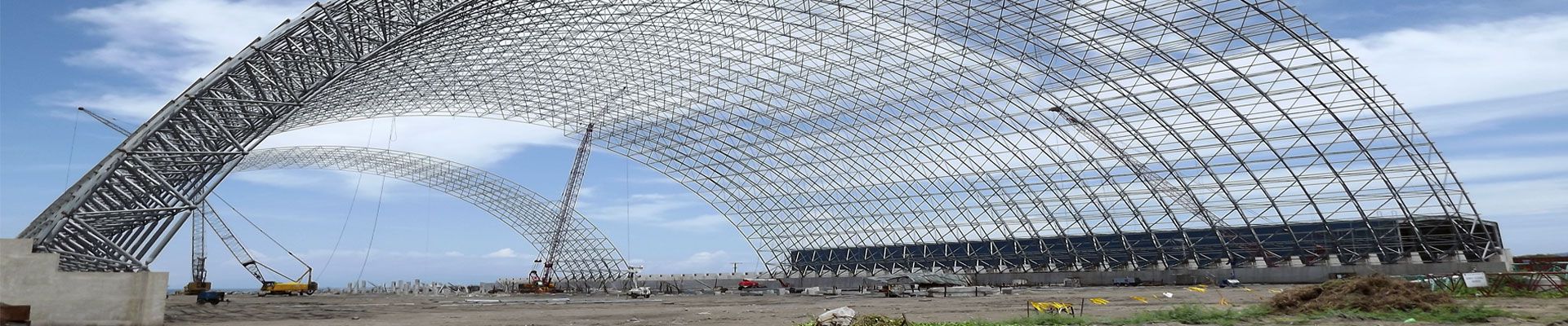
With the continuous development of society and economy, infrastructure construction requires more building materials, and the production capacity of cement plants needs to be continuously expanded. This places higher demands on the building area and storage capacity of storage warehouses. As an important storage facility for cement plants, clinker silos naturally face the urgent need to increase their storage capacity. This article describes the design and construction process of the steel roof for an 85m diameter clinker silo in a cement plant, with a storage capacity of approximately 285,000 tons.
1.1 Project Overview
This project is a winter storage warehouse for cement clinker. The concrete circular silo has a diameter of 85m, a wall thickness of 0.9m, and a height of 27m. The truncated pyramidal steel roof space structure has a clear height of 28.16m and a rise-to-span ratio of approximately 1/3. The lower chord of the spatial structure is supported by 40 unidirectional sliding supports, with the center of each support sphere at an elevation of 27.470m. The H-shaped steel platform on the top of the silo has a diameter of 18.5m (15.5 + 2 × 1.5) and a surface elevation of 56.230m. It is supported on the top of the truncated pyramidal spatial structure via brackets (15.5m in diameter). The steel platform houses dust collectors, steel corridors, belt conveyors, and a roof with maintenance hoists. The roof is a single layer of 750-type color steel sheet.
1.2 Design Parameters
The steel spatial structure uses Q235B steel pipes with a stress ratio of 0.85. The slenderness ratio of both tension and compression members is 150. The roof’s dead load is 0.2 kN/m², live load is 0.5 kN/m² (no snow pressure in the south), ash load is 0.5 kN/m², and wind load is 0.35 kN/m² (R=100). Based on the height, a wind pressure height variation coefficient is used for Class B sites, and a wind vibration coefficient of 1.50 is considered. Temperature differences are considered to be 60℃ and -30℃.
The dead load of the steel platform floor is the self-weight of the H-beam steel platform + the self-weight of the checkered steel plate + the dead load of the process equipment. The live load of the steel platform floor is the live load of the process equipment, taking into account the vibration coefficient. For safety, a nonlinear stability analysis is performed on the frustum spatial structure. The initial geometric defect distribution adopts the lowest-order buckling mode of the structure, the maximum defect value is 1/300 of the span, and the safety factor K is 4.2.
1.3 Calculation Results
The steel space structure of the clinker silo was designed using the MSGS spatial structure program from the China Academy of Building Research, and verified by the MST spatial structure program from Zhejiang University. Stability calculations and construction verification were performed using the 3D3S steel structure program from Tongji University. The deflection value of the clinker silo frustum spatial structure is 80mm, far less than the deflection control value of 85000/400 = 215mm, and the steel consumption is less than 55kg/m². The steel consumption of the 12.3m high silo roof spatial structure is less than 50kg/m². The maximum pipe diameter is 180mm × 10mm, the maximum bolt size is M52, and the maximum bolt ball size is D260.
The number of structural formations is taken as 25. Calculations show that the mass participation coefficient in the XYZ directions basically meets the requirement of over 90% (90.60%, 91.16%, 87.57%). The period of the first formation is 0.53s. The first three formations are shown in Figures 2-4.
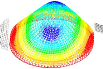
Figure 2 First-order formation (X-direction translation), T=0.53s
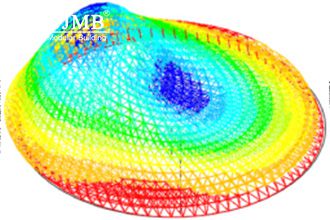
Figure 3 Second-order formation (Y-direction translation), T=0.51s
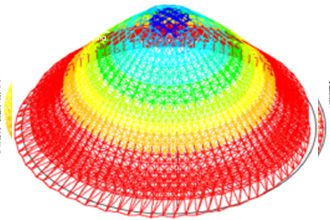
Figure 4 Third-order formation (torsional), T=0.39s
The linear stability mode coefficient is 60.0, and the load level of the imperfect (initial geometric defects) structure is 40.1, indicating that the structural stability meets the requirements.
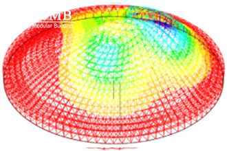
Figure 5 Linear stability mode, stability coefficient 60.0
2.Processing and Inspection
2.1 Inspection Standards
The spatial structure of this project was sampled and inspected by the owner. Ten members from five categories were selected for a physical combined tensile test. The test standards are JG/T10 “Steel Space Structure Bolted Ball Joints” and GB/T 16939 “High-strength Bolts for Steel Space Structure Bolted Ball Joints”. This test method is no longer described in the current steel structure acceptance standards, but it is still recognized by relevant units.
2.2 Inspection Results All submitted samples passed inspection, and the issued inspection reports showed three results:
(1) Bolt breakage (data meets the corresponding bolt mechanical tensile load value, unit: kN);
(2) Steel pipe breakage (data meets the technical requirement of 370~500MPa);
(3) Weld breakage (data meets the technical requirement of steel pipe of 370-500MPa), see Figures 6 and 7.
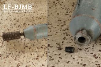
Figure 6: Rod test fixture and test results (Class 1)
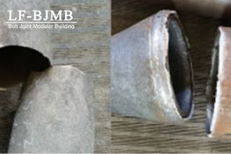
Figure 7: Rod test results (Class 2 and Class 3)
3.Construction Method
3.1 Starting Point of Frustum Space Structure
This project is a high-risk engineering project exceeding a certain scale. A special construction plan was prepared and an expert review meeting was held. The project started by using chemical anchors and steel wire rope backing cables on the reservoir wall to strictly control deformation until a closed loop was formed.
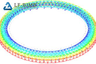
Figure 9. Backstay cable closure loop (maximum displacement 3.5mm)
3.2 Spatial Structure Closure Acceptance
Dynamic monitoring of key points throughout the process; assembly using bolted ball joint modules, working upwards ring by ring; the monitored displacement and calculated values for the construction section showed a consistency of over 90%, ensuring process safety and quality control.
No safety accidents occurred during construction, and the construction quality was recognized by the client, resulting in a smooth project acceptance. The design drawings handled details such as the eaves well; a water-retaining protrusion and embedded plate were installed around the outer edge of the support for fixing the angle iron at the eaves. Excellent dustproofing and aesthetic effects were achieved from the roof of the truncated pyramidal spatial structure to the roof of the warehouse space structure.
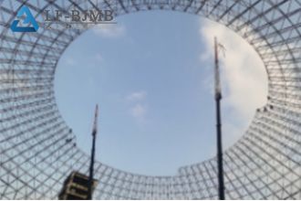
Figure 10. Construction process of the truncated pyramidal spatial structure
4.Conclusion
The design and development adopted a three-layer spatial structure reinforcement ring at the support, effectively controlling the diameter of the spatial structure bolts and avoiding welded balls, laying the groundwork for efficient installation and quality assurance. Dynamic calculation analysis was used during construction, with real-time monitoring of key points in the spatial structure. The completion of this project involved collaboration from multiple departments and disciplines, and is intended for reference and exchange among industry colleagues.


