





 About Us
 2026-05-08
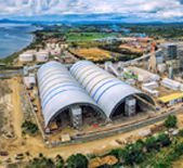
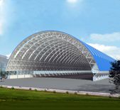
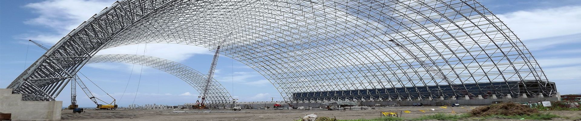
As environmental protection requirements continue to rise, an increasing number of thermal power plants, steel mills, and port coal yards are adopting enclosed dry coal storage shed structures to reduce dust pollution and improve working conditions. For large-span coal storage sheds, steel space frame structures have become the mainstream solution due to their high span capacity, uniform stress distribution, and high construction efficiency.
This paper uses the “Datang Xigu 110m and 122m Span Dry Coal Shed Steel Truss Project” as a case study to analyze key technologies in structural layout, truss selection, load design, wind stability, and thermal stress control for ultra-large-span coal sheds.
1.Project Overview
The Xigu Dry Coal Shed Steel Truss Project is a key component of the fuel supply system for the Datang Xigu 2x330MW Combined Heat and Power (CHP) Plant’s “phase-out and expansion” project. As the structure is being built on an existing site, the design must comprehensively consider the integration and coordination of surrounding existing buildings, roads, and new sub-projects while meeting process requirements, presenting significant challenges for the layout and elevation planning; Furthermore, the complex stress conditions and numerous influencing factors of the large-span dry coal shed necessitate in-depth analysis and comparison at every stage of the design to ensure safety and rationality.
2.Layout and Selection
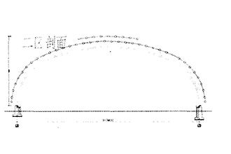
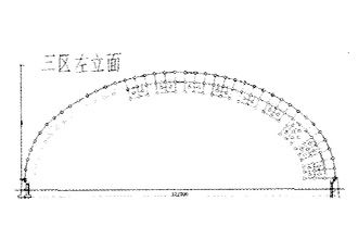
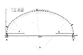
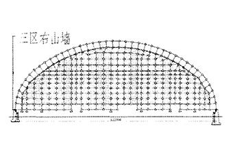
Taking into account the plan locations of the railway on the south side, the road on the north side, the newly constructed Belt No. 13, Transfer Station No. 5, the existing Underground Coal Conveyor No. 6, and the three existing coal pits in the north and south, to ensure that the foundation does not interfere with these structures, we divided the site into three zones: Zone 1, with an outer chord span of 110 m and a length of 121.5 m, with the boundary line located on the inner side of Belt No. 13; Zone 2: 103.4 m outer chord span, 45 m long, with the boundary line located on the inner side of Transfer Station No. 5; Zone 3: 122 m outer chord span, 105.5 m long, with the boundary line located on the outer side of the two coal pits. The left side of Zone 1 and the right side of Zone 3 are enclosed by gable walls.
Since even the largest semi-circular cylindrical surface grid shell cannot meet the bucket wheel excavator clearance requirements under the existing plan dimensions, a three-centered cylindrical surface was selected. This design can, while meeting the bucket wheel excavator operational clearance requirements, moderately reduce the grid shell’s rise and decrease the height of the windward face. Based on the theory that the three centers are tangent to each other and ensuring that all cross-sectional members of the grid shell have identical dimensions, and using the fitting formula from Reference 1 (a paper by the Central South Institute), we developed a VB program capable of fitting different trisecant curves for the same span. We then performed calculations and comparisons. By analyzing and comparing truss structures formed by multiple trisecant profiles that meet the process constraints, we selected the most economical model with a rise of 40.138 m and a thickness of 3.5 m.
In Zone 3, although the increased span already meets process requirements, a three-centered cylindrical space frame form is still adopted to reduce the rise. Due to the increased span, the thickness is increased to 3.8 m to enhance structural stiffness.
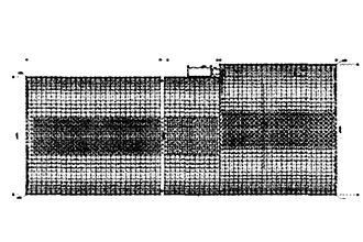
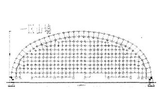
The truss structure in all three zones is a three-center cylindrical truss with a three-layer roof section: the longitudinal grid length is 4.5 m, with a 4 m section in Zone 3; the grid cross-sectional dimension is 4 m; the truss height in Zone 1 is 40.138 m, in Zone 2 is 41.138 m, and in Zone 3 is 45.908 m. The thickness of the skylights is 3 m across all sections. Refer to Figure 1 for detailed plan and sectional views.

3.Structural Analysis and Design
3.1 Load Calculations
(1) Dead Loads
The loads from purlins and roof panels are 0.2 kN/m², and the self-weight of the walkway is 0.15 kN/m².
(2) Live Loads
The roof live load is 0.5 kN/m², and the walkway live load is 1 kN/m². Note: The live load for half a span considers only the roof live load; the walkway load is not included.
(3) Ash Load
According to data provided by the Northwest Electric Power Design Institute, the ash load for the power plant is 0.
(4) Snow Load
The 50-year return period basic snow load is 0.15 kN/m². Since snow loads and live loads are not considered simultaneously, only the live load should be considered in this example.
(5) Wind Loads
The basic wind pressure for a 50-year return period is 0.3 kN/m². Since wind loads play a significant role in large-span lightweight structures, the adjusted basic wind pressure value in this example is taken as the 100-year return period value of 0.35 kN/m². The wind load shape coefficient is determined according to the provisions for enclosed arched roofs in Table 7.3.1-4 of the load code, with values as shown in Figure 2.
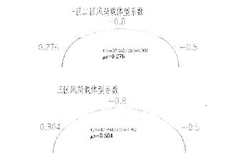
Figure 2
The wind pressure height variation coefficient is referenced from Table 7.2.1-B.
The wind vibration coefficient is taken as 2.0, based on the conclusions in Reference 2.
(6) Temperature Difference Effects
The temperature difference effect accounts for the difference between the construction temperature and the local annual average minimum and maximum temperatures. The construction period for this project is July–October 2009; a positive temperature difference of 20°C and a negative temperature difference of –40°C are considered.
(7) Seismic Action
Seismic zone 8, seismic group 2.
Primary load combinations:
(1) 1.2 times dead load + 1.4 times live load + positive and negative temperature differences.
(2) 1.2 times dead load + 1.4 times live load + 1.4 × 0.6 times left (right) wind load + positive and negative temperature differences.
(3) 1.2 times dead load + 1.4 × 0.7 times live load + 1.4 times left (right) wind load + positive and negative temperature differences.
(4) 1.0 dead load + 1.4 left (right) wind + positive and negative temperature differences.
(5) 1.2 dead load + 1.4 left (right) span live load + 1.4 × 0.6 left (right) wind + positive and negative temperature differences.
(6) 1.0 dead load + 1.4 gable wall left (right) wind + positive and negative temperature differences.
(7) 1.2 dead load + 0.5 live load + 0.2 left (right) wind load + 1.3 horizontal seismic action + 0.5 vertical seismic action.
The design of the roof grid shell structure for this project was analyzed and designed using the MSGS 8.0.4 beta software developed by the Institute of Building Structures at the China Academy of Building Research, with fully hinged supports. To enhance safety margins, members with a minimum size of D75x3.75 were used, with a strength control value of 215 × 0.9 = 193 N/mm². Considering the complexity of the stress state in the upper and lower chords of the space frame under different load combinations—where tension members may become compression members—the slenderness ratio for both tension and compression members in this project was controlled at 180.
Calculations revealed that the cross-sections of the longitudinal members at the supports were relatively large, a phenomenon caused by thermal stress. To relieve this thermal stress, every other connection member in the longitudinal members at the supports was removed. After this adjustment, the internal forces near the truss supports became more reasonable.
The main analysis results for this project are as follows:
Zone 1: Maximum compression 1189 kN, maximum tension 870 kN, maximum deflection 189.3 mm.
In Zone 2, the maximum compression force is 1,017 kN, the maximum tensile force is 1,211 kN, and the maximum deflection is 193.7 mm.
In Zone 3, the maximum compression force is 1,113 kN, the maximum tensile force is 924 kN, and the maximum deflection is 178.1 mm.
4. Verification
All three sections of this project were verified using MIDAS software and meet the design requirements.
(1) When constructing a long-span space frame structure on an existing coal yard, various objective conditions must be comprehensively considered to determine the layout.
(2) Due to the large amount of steel required for long-span space frames, various design options must be compared to select the most economical and reasonable solution.
(3) Loads and load combinations must be considered comprehensively and in detail, with analysis of the most unfavorable combinations, to ensure a safe design outcome.


