






 About Us
 2025-08-27
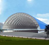
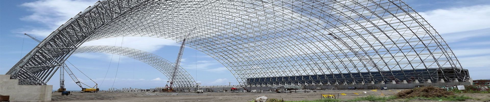
Space frame structures for sports arenas have seen significant development over the past 30 years and are now widely used both domestically and internationally. These structures offer flexible planar layouts and aesthetically pleasing spatial forms, facilitating architectural design and decorative finishes. They can accommodate buildings with varying spans, planar shapes, support conditions, and functional requirements.
Now let’s take a look at the selection and construction of space frame structures.
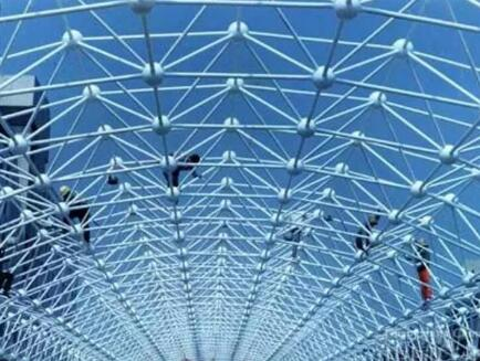
How to select the model?
Structural System
By structural composition: Typically classified as double-layer or triple-layer space frames.
By support conditions: Includes perimeter-supported, point-supported, and hybrid forms combining perimeter and point support.
By frame configuration: Categorized into cross-truss systems composed of two-way or three-way planar trusses, and spatial pyramidal systems formed by triangular or quadrangular pyramids.
Basic Principles for Model Selection
The selection of space frame types should be determined through a comprehensive analysis that considers factors such as the project’s plan geometry, architectural requirements, load and span dimensions, support conditions, and cost.
- For large-span structures: Three-way intersecting space frames and triangular cone space frames are preferred.
- For planar cross-truss systems: Orthogonally aligned configurations are recommended for square or near-square plans; orthogonally skewed configurations are recommended for rectangular plans; skewed-skewed configurations are not recommended.
- For tetrahedral systems: Orthogonally aligned configurations provide uniform stress distribution and optimal stiffness; orthogonally aligned with voids saves steel and facilitates daylighting/ventilation; skewed and star configurations maximize material strength utilization.
4. For planar shapes of triangles, hexagons, or circles: Triangular pyramid systems are the preferred choice.
5. Support method selection: Perimeter supports are suitable for large- and medium-span structures; point supports offer flexible layout for buildings with large column spacings, such as factories and warehouses; hybrid supports are appropriate for aircraft hangars or assembly workshops.
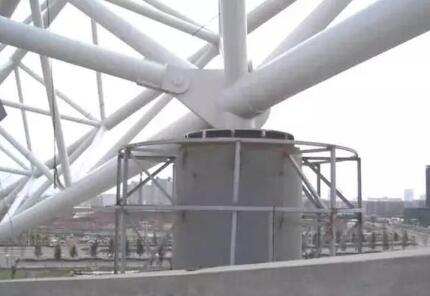
How to Construct?
The construction and installation methods for sports stadium space frame structures primarily fall into two categories: one involves ground-assembled, integrated jacking and lifting; the other employs high-altitude positioning with modular assembly.
High-Altitude Modular Assembly
1. When assembling small sub-units or members directly at height, the sequence must ensure assembly precision and minimize cumulative errors. During cantilever construction, first assemble a structural system capable of supporting its own weight, then progressively expand outward. Continuously verify the reference axis position, elevation, and deviations during assembly, correcting promptly as needed.
2. When erecting assembly scaffolding, position support points at the lower chord nodes. Verify the scaffolding’s load-bearing capacity and stability; conduct load tests if necessary to ensure safety and reliability. Measures must be taken beneath scaffold supports to prevent foundation settlement.
3. During scaffold dismantling, prevent concentrated loading at individual support points. Supports should be removed either by proportional, phased lowering based on structural deflection values at each point, or by equal-step lowering with increments not exceeding 10mm per step.
Overall Lifting
1. The space frame can be lifted by installing lifting equipment on the structure, or it can be lifted concurrently with column slipform construction, in which case the space frame serves as a lifting platform.
2. The working load capacity of lifting equipment shall be determined by multiplying the rated capacity by a reduction factor: Through-hole hydraulic jacks: 0.5–0.6, Electric screw jack lifting plates: 0.7–0.8, Other equipment: determined through testing.
3. Synchronization must be ensured during truss lifting. Permissible lifting differences between adjacent points and between the highest and lowest points shall be verified through calculations. Permissible lifting difference between adjacent points: When using lifting jacks, it shall be 1/400 of the distance between neighboring points, not exceeding 15mm; when using through-hole hydraulic jacks, it shall be 1/250 of the distance between adjacent points, not exceeding 25mm. Permissible lifting difference between the highest and lowest points: When using lifting plates, it shall be 35 mm; when using through-hole hydraulic jacks, it shall be 50 mm.
- The resultant force point of the lifting equipment shall align with the lifting points, with a permissible deviation of 10 mm.
- Stability calculations shall be performed for the lower support columns in the overall lifting method.


